One CAD path, five kinds of physics.
A STEP model should not disappear when the question changes. The new Copilot missions reuse pinned CAD tetrahedra for directional wind loading, steady temperature, diffusion, rigid-stop contact and damage-initiation screening—and every returned result stays orbitable in 3D.
Direction is a vector, not a dropdown label
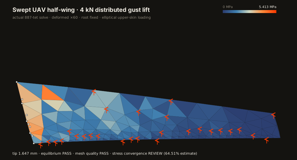
The UAV live solve now accepts a global [x,y,z] vector. The browser exposes XY, XZ and YZ planes plus full XYZ space; angle, azimuth and elevation are converted to that vector, and the server normalizes it before distributing the requested resultant over the upper-surface CAD nodes.
POST /demo/cad/uav-wing-gust
{ "load_n": 4000, "direction": [1, 2, 3] }

resultant = 4000 · [1,2,3] / √14
          = [1069.0, 2138.1, 3207.1] N
The moving orange dashes are an animation of the applied load direction. They are deliberately not called airflow, CFD or transient response. The colour contour remains the verified static structural solution.
The Copilot starters are CAD solves now
Each starter names run_cad_case, a bounded tool that selects one of three hash-pinned STEP assets. It cannot silently replace the geometry with a beam or hand-written plate. The medium-detail 2020 extrusion bracket comes from the FreeCAD Parts Library. The wing source is NASA's public Common Research Model CAD; its untouched 53.8 MB, 11,394-face file is retained for provenance, while the keyless solve uses the explicitly identified source-derived envelope that fits the interactive response budget.
NASA publishes the original CRM wing in STEP format on its official geometry page. The bracket is attributed to the FreeCAD Parts Library. Source URL, author, license and SHA-256 travel with every result.
| CAD mission | Real result | Evidence |
|---|---|---|
| UAV, oblique XYZ wind load | 4.126 MPa element peak for [1,2,3] | REVIEW: refine stress |
| NASA envelope, 293.15→373.15 K | 3D steady temperature | PASS |
| UAV, root→tip diffusion | concentration 1→0 | PASS |
| Bracket, 150 N rigid stop | 0.399 MPa contact pressure | PASS |
| Bracket, 150 N damage screen | max element index 0.764 | REVIEW: concept mesh |
What “damage” means here
The interactive bracket mission computes a stress-based damage-initiation index, von Mises / concept allowable. It is useful for locating regions that approach the comparison threshold. It is not damage evolution, fatigue life, crack growth or calibrated failure. That distinction is encoded in the tool result and repeated in the starter prompt.
3D is the common output contract
The Copilot viewer now receives true XYZ coordinates for every mission. Iso, XY, XZ and YZ are camera choices over the same geometry, not separate flattened result files. Heat, concentration, displacement, von Mises stress and damage index are selectable scalar fields; supports, loads, mesh and deformed shape remain independent overlays.